
Convert Ungrounded to Resistance-Grounded Systems
Resistance grounding protects a system against transient overvoltages caused by intermittent ground faults and it provides a method to locate ground faults. (Transient overvoltages and inability to locate ground fault are the most common safety issues with ungrounded systems.)
Conversion of delta-connected or wye-connected sources with inaccessible neutrals require a zig-zag transformer to derive an artificial neutral for connection to a neutral grounding resistors (NGR). The artificial neutral is only used for the NGR and not for distribution. During normal operation the only current that flows in the zig-zag transformer is an extremely small magnetizing current. When one phase is grounded, the NGR and the zig-zag transformer provide a path for ground-fault current to flow.
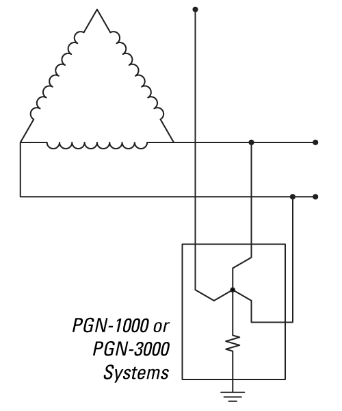
Figure 1
Design Note 1: The PGN Families of NGR systems include the zig-zag transformer when specified.
Design Note 2: The PGN system requires a 3-phase connection to the existing power system, typically at the main transformer or switchgear. See Figure 1.
Design Note 3: The resistor let-through current must be greater than the system capacitive charging current (see Section I).
Design Note 4: Protection, coordination, and annunciation systems depend on the integrity of the NGR. PGN-1000 Series has an option for resistor monitoring, whereas the PGN-3000 Series includes resistor monitoring.
Convert Solidly Grounded to Resistance-Grounded Systems
Resistance grounding protects a system against Arc Flash Hazards caused by ground faults and provides a method for continuous operation or an orderly shut-down procedure. (Ground faults are estimated to be 95% of all electrical faults.)
Since the neutral point of the power source is available, the solid connection between neutral and ground is replaced with a grounding resistor. This resistor limits ground fault current to a pre-determined value, typically 5 A for 480 V systems (the system capacitive charging current is usually less than 3 A). By limiting the ground fault current to 5 A or less, there are no Arc-Flash Hazards associated with ground faults. This allows for continuous operation during the first ground fault.
During a ground fault on a Resistance Grounded (RG) system, a voltage shift occurs (the same shift experienced on Ungrounded systems). The faulted phase collapses to ~0 V, the non-faulted phases rise to line-to-line voltage with respect to ground, and the neutral point rises to line-to-neutral voltage with respect to ground.
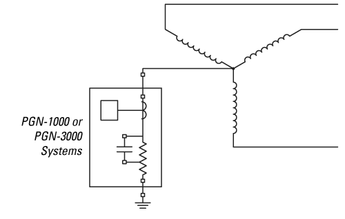 Figure 2
Design Note 1:
Figure 2
Design Note 1: The PGN system requires a neutral connection to the existing power system, typically at the main transformer or switchgear.
See Figure 2.
Design Note 2: The voltage shift requires equipment to be fully rated at line-to-line voltage with respect to ground. This may require TVSSs, VFDs, meters, etc. to be reconfigured or replaced.
Design Note 3: The voltage shift also restricts neutral distribution. The neutral cannot be distributed due to its potential during ground faults. Single-phase line-to-neutral-voltage loads must be served by a 1:1 isolation transformer or converted to line-to-line loads.
Design Note 4: The resistor let-through current must be greater than the system capacitive charging current
(see Section I).
Design Note 5: Protection, coordination, and annunciation systems depend on the integrity of the NGR. PGN-1000 Series has an option for resistor monitoring, whereas the PGN-3000 Series includes resistor monitoring.